

Introduction :
After the first step, this second step intent to build a small and very simple TEC cooling system. We just will adapt the aluminium finger we already have, add a small connector and a TEC module, and make a simple control box for this module. No temperature regulation at this time. This mod must still be "low cost".
Choosing the module :
There is many constraints for the Petier module. Peltier's size is the most important. Our module must be smaller than 25mm x 25mm to just fit the camera's body. This module must also be standard, in order to be found everywhere.
According to my previous experience in passive cooling, the CMOS sensor seams to dissipate about 250mW (average). The CMOS sensor package's thermal resistance is about 80 °C/W. On most TEC modules, Delta T is about 60 °C. Pumping a lot more than 1 W is useless. Pumping these 1 W is easy, even with a small TEC. To be efficient, a TEC module must be used close to the maximum current and voltage. So, the question is : how many Watts are we able to dissipate from the hot side ? Conclusion : smaller is better !
The NL1012T-01AC from Marlow Industries (9mm x 9mm Qmax = 2.1 W Vmax = 3.7 V Imax = 1 A) is certainly one of the best choices. But I only have a 6.9 W 15mm x 15mm (Vmax = 3.7 V, Imax = 2 A) module.
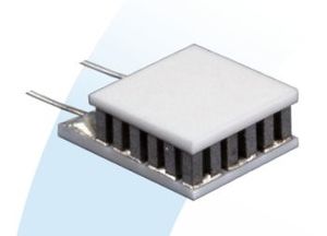
I found a nice 6.6mm x 6.6mm tiny TEC (from Laird, Qmax = 1.6 W, Vmax = 2.3 V, Imax = 1.2A) . It will take place between the CMOS and the cooling finger.
Choosing the heat sink :
The heat sink will depend on the TEC. I made some simulations with my tiny TEC specifications :
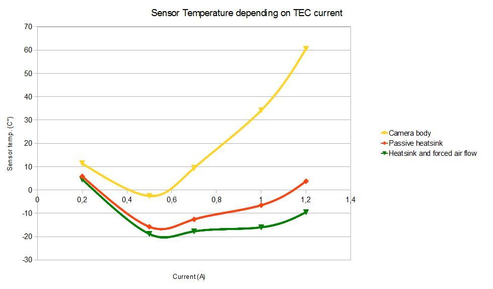
All the camera's connectors are on the body's back side. We have no choice : we must use a passive heat sink, or have a fan not bigger than 30mm x 30mm. A 60mm round or a 45mm x 45mm square heat sink would be great.
The simulations are based on a 10 C°/W passive heat sink, and a 5.5 C°/W forced air heat sink. The camera's body thermal resistance used here is based on the step 1 passive cooling results. If you want more details, just send me a message.
I don't want to freeze my sensor, I just want to cool it a bit. No heat sink for me at this time. I will have to manage dew issues.
The new finger :
My new cold finger is very simple. It's just a bit shorter than the previous one (2mm, but it depends on the TEC module).
The connector :
I don't want to drill my camera's body, and the LED is to powerfull for me.We can use the led hole to pass a 4 strand wire. Two strands for the TEC, two for the futur temperature sensor (cf. step 3). A clean way to remove the LED to let the hole free is explained there : Removing the QHY5's LED
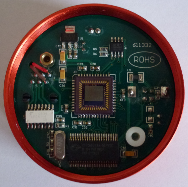
An other solution is to use pin 1 and 2 (NC and Ground) of the ST4 RJ12 connector to power the Peltier TEC. I drilled a small hole, near the ST4 connector, and solder two wires (red and the brown. Pin 1 is not connected, and pin 2 has a galvanic isolation, so, the camera won't be affected. These two wires will power up my Peltier TEC.
The Peltier TEC is set in place using thermal paste :

The control box :
At this time, we don't use a temperature sensor, so we don't have any feedback. The best way to get some temperature stability is to feed our TEC with a constant current. We need a tunable current source, delivering up to 1 Amps at about 2 volts. As you can see on my simulations, the best results are achieved with a 500mA current at 1 V.
I used a fixed 500 mA current source, with an LM317 as regulator. It's a very simple design :

Results :
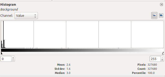
A first try without any heatsink gives these results (30s dark, gain at 10, ambiante temperature at 24°C)
Peltier TEC off :

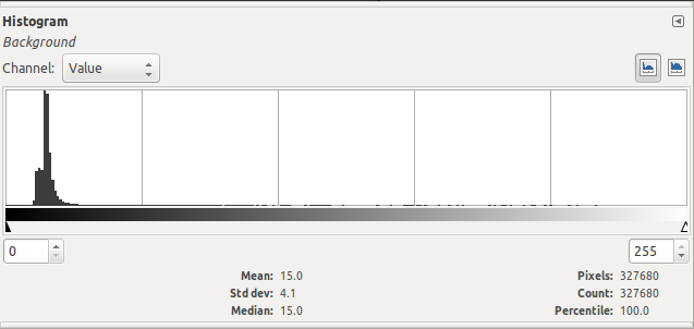
Peltier TEC on :

These results can't be compared to those of the "cooling step 1", the qastrocam-g2 gain handling has changed.


